


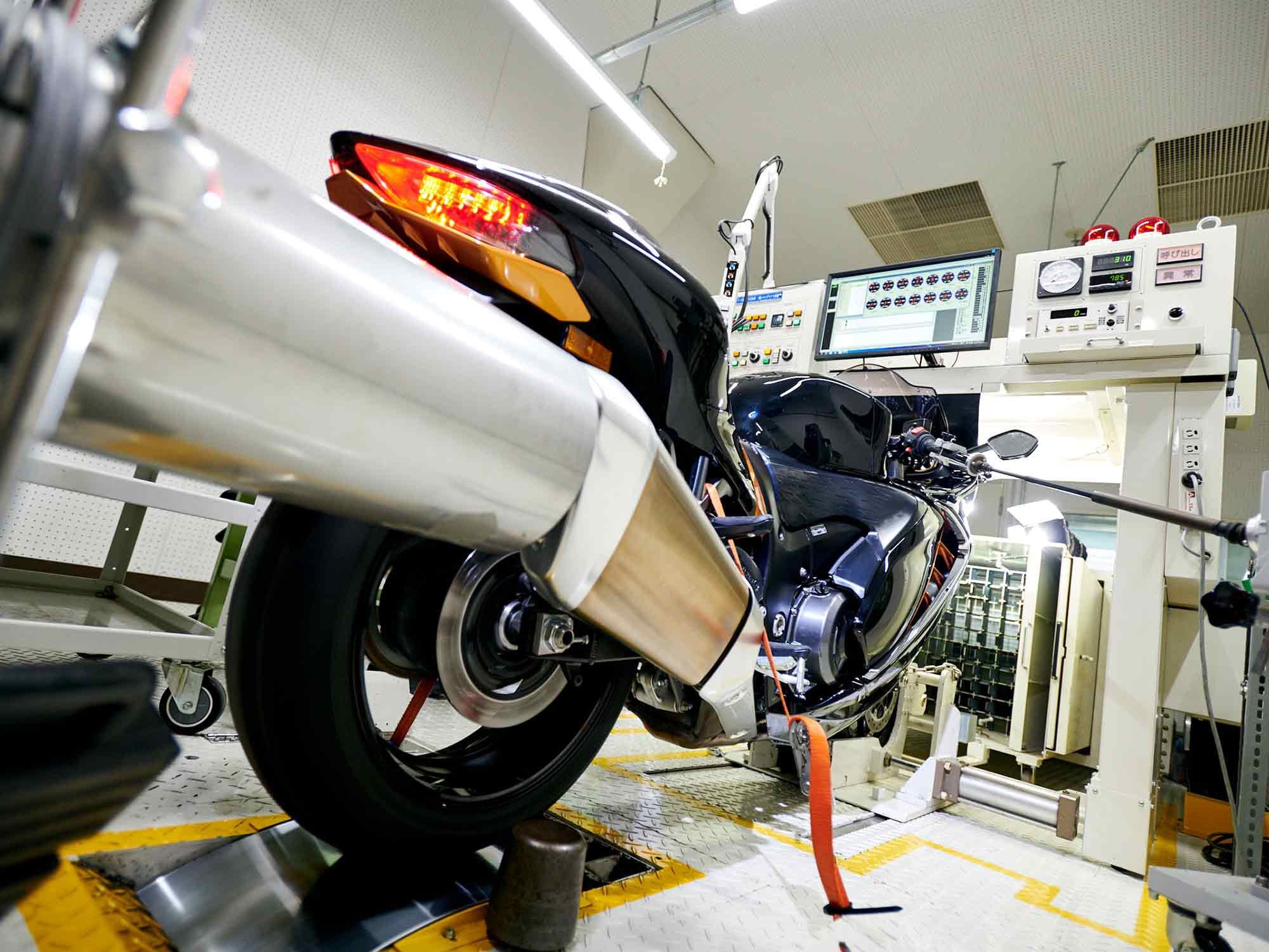
Euro 5 emissions regulations had much to do with the changes to the 2022 Suzuki Hayabusa (shown here during sound testing). (Suzuki/)The emissions reductions required by the new Euro 5 standards are the underlying reason for Suzuki updating the Hayabusa, thereby enabling its sales to continue. The reductions in comparison to Euro 4 are 12 percent in carbon monoxide (CO), 41 percent in unburned hydrocarbons (UHC), and 33 percent in nitrogen oxides (NOx), in effect from January 1, 2020.
The Gen 2 Hayabusa carried two exhaust catalysts, located forward at the header pipe junctions. The new Gen 3 Hayabusa adds downstream cats located in the mufflers. Contact between hot exhaust gas and the chemically active catalyst pushes chemical change in the desired directions: toward completing the combustion of UHC and carbon monoxide and reduction of smog-forming nitrogen oxides.
As in the previous model, to assist exhaust oxidation catalysts in their work of completing combustion of UHC and carbon monoxide to form carbon dioxide, extra oxygen is provided by Suzuki’s “PAIR” pulsed secondary air-injection system (this is equivalent to the “smog pumps” that were once common on auto engines).
The 2022 Hayabusa features catalysts in its mufflers. (Suzuki/)For years, It was routine to give sportbike engines fairly long cam timings to boost cylinder filling at higher rpm, even though doing so allowed some mixture to be back-pumped at lower revs, resulting in reduced torque at bottom-to-mid rpm. Such long timings required considerable valve overlap.
Mixture control becomes more complicated during rapid changes of load. Additional control over engine fuel mixture during rapid load changes is provided by the Gen 3 Hayabusa’s throttle-by-wire system.
During the carburetor era it was possible for the rider to turn the throttle so fast that fuel could not keep up with air rushing into the engine. The result was a lean stumble. The CV carburetor of the 1980s overcame this by providing a secondary throttle slide whose opening was slightly delayed by venturi vacuum: No matter how quickly the rider snapped the throttle, the vacuum-controlled slide would maintain the venturi velocity necessary to keep adequate fuel flowing.
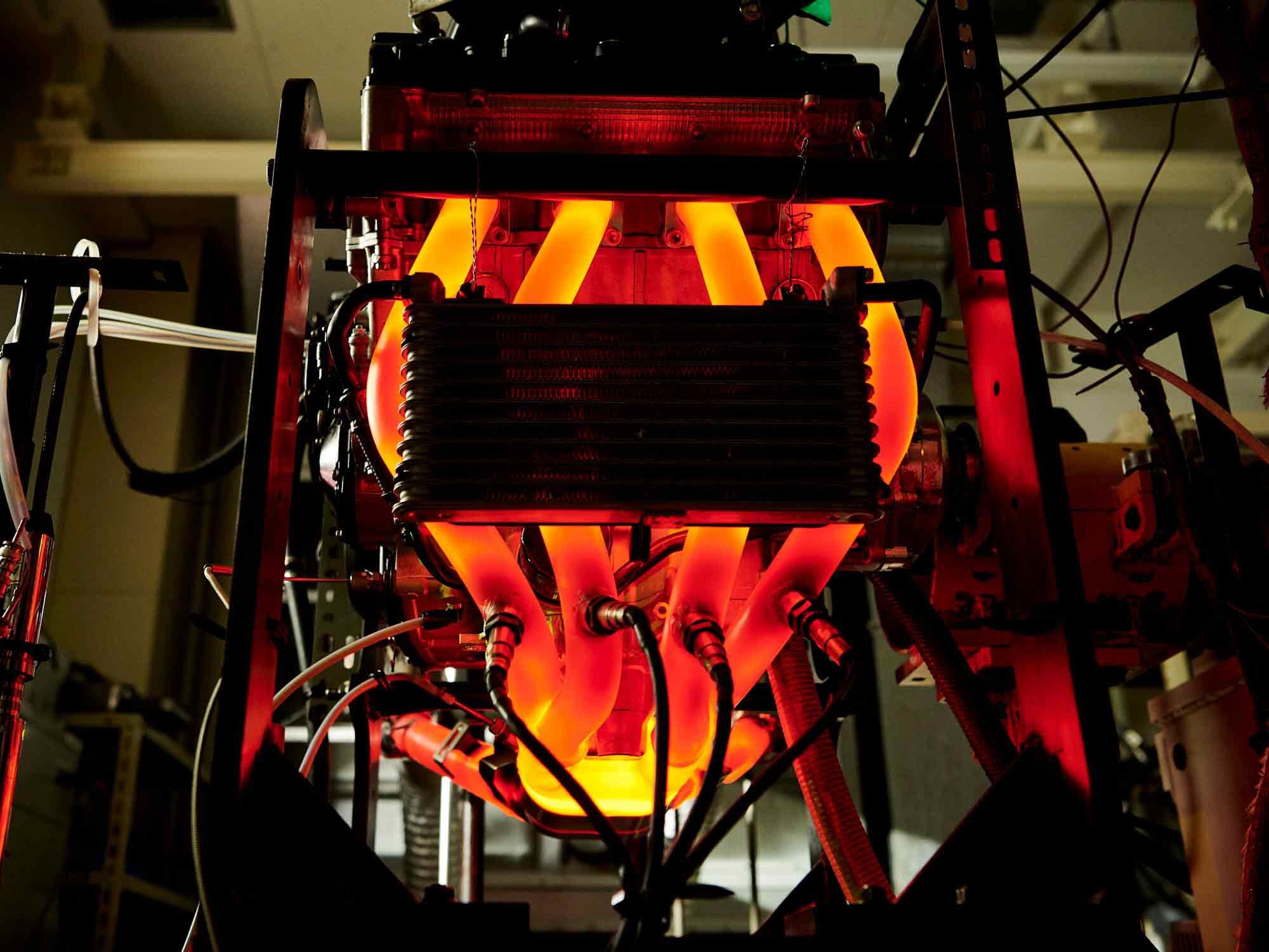
Contact between the hot exhaust gas and the catalytic converter (the brightest glowing area) completes the combustion of UHC and carbon monoxide and reduces smog-forming nitrogen oxide. (Suzuki/)When fuel injection arrived in the ’90s, the throttle butterfly in each cylinder’s throttle body was controlled directly by the rider via a steel throttle cable, so once again it became possible for the rider to open the throttle too fast. Suzuki’s solution was to place a secondary throttle plate, controlled by the ECU, in each throttle body. Mimicking the action of a CV carb’s secondary throttle, this plate would open at a rate that enabled the fuel system to keep up. This was called Suzuki Dual Throttle Valve (SDTV).
Updating to modern electronics, the Hayabusa now employs throttle-by-wire, a copper throttle “cable.” When the rider moves the throttle grip, an electronic sensor (the throttle position sensor, or TPS) reports its angle, and the ECU interprets this as a torque demand. It then opens the throttle and supplies fuel appropriate to that demand. The result is more accurate mixture control during rapid throttle movement. When mixture is correct—neither rich nor lean—fuel has the best chance of burning completely, thereby both boosting response and reducing emissions.
Previously each cylinder’s intake tract contained two injectors: a lower one beneath the rider-controlled throttle plate and an upper side injector aimed at the secondary throttle plate. In the 2022 throttle-by-wire Hayabusa, there is no secondary throttle plate, so the upper injector’s fuel jet is broken up by hitting a fixed metal plate whose surface is parallel to the airflow. On many bikes, the upper injectors, called “showerheads,” hover over each intake’s bellmouth. On the Hayabusa, where height is at a premium, the upper injectors are “side feeders” that spray at an angle through the sides of the intakes. Intake tract length has been increased by a half-inch. Suzuki states that fuel breakup against the fixed plate contributes a 2 percent gain to low- and midrange torque. The injectors are altered to produce a finer droplet size as well.
The 2022 Hayabusa’s upper fuel injectors spray against a fixed plate in the throttle body. (Suzuki/)How does fuel droplet size affect power, fuel consumption, and emissions? Any fuel system dependent upon the rapid evaporation of a spray produces a range of droplet sizes (the same is true of the liquid propellants injected into rocket engine thrust chambers). Depending on the size and number of the largest droplets produced, some fuel may not have time to evaporate and fully take part in combustion. Such unburned fuel, by slightly cooling combustion, reduces power and increases both fuel consumption and UHC emissions.
Detail Changes to Combustion Chambers
Suzuki’s provided press materials compare the Gen 2 and 2022 chambers. In Gen 2 there is a triangular cusp of squish area between the pairs of intake valves (squish is those parts of piston crown and head that come very close to each other at TDC, to rapidly “squish” out the mixture between them, forming fast jets that usefully accelerate combustion).
Air quality agencies dislike squish because it can act to cool or “quench” combustion by close proximity to cool metal surfaces, increasing the production of UHC. Rule of thumb in the past has been to devote 15 percent of four-stroke piston crown area to squish, but times have changed. When emissions requirements deny engineers one way to get what they need, they work to get the same effect by other means. A much stronger potential source of turbulence to speed combustion is the inrush of high-velocity mixture during the intake stroke, and the best way to prevent loss of that turbulence-producing velocity during the following compression stroke is by making the inside surfaces of head and piston crown as smooth as possible. The new Hayabusa’s reduced valve overlap requires fewer deep valve clearance notches in the piston crown.
The third-generation Hayabusa combustion chamber. (Suzuki/)Suzuki found it could turn the loss of those squish cusps into increased “curtain area” to increase airflow at low valve lift. Curtain area is valve lift, multiplied times valve head circumference. Result: a flow gain of 5 percent at lower valve lifts. Also interesting is a 1mm reduction in throttle-body diameter, from 44 to 43mm, which slightly increases intake velocity. When change is forced upon you, exploit it as an opportunity.
Shorter Cam Timings Increase Valve Accelerations
Suzuki has increased exhaust valve lift to be essentially equal to intake lift and has somewhat reduced the number of degrees during which valves are open. Because both changes require more rapid valve accelerations, stiffer valve springs have been adopted. To carry the doubly increased load of these springs plus higher valve acceleration, cam lobes have been made wider so that the oil film between them and the valve tappets is not overloaded; the bigger the surfer, the bigger the board.
Sharp-eyed readers will see that to make the torque gains in the range of 3,300–7,000 rpm, some compromise has been necessary at higher rpm. A suite of changes to cam timing, possibly longer exhaust header pipe length, airbox resonance rpm range, and the lengthening of the intake tracts by half an inch, are probably responsible.
Altered Cam Timings Reduce UHC Emissions
Overlap is that time near TDC at the end of the exhaust stroke when the intake valves have already begun to open before top center, but the exhausts are still in the late stages of closing, slightly after top center. Valve overlap boosts performance because: 1) by allowing more time for valve opening and closing, valves can accurately follow cam contours without extremely stiff springs, and 2) if the exhaust pipes are properly dimensioned, a negative pipe wave can return to the cylinder to extract any residual exhaust gas above the piston and then travel past the partly open intake valves to begin the intake process early, even before the piston has begun to move downward on its intake stroke.
Cam timing was altered to reduce unburned hydrocarbon emissions on the 2022 Suzuki Hayabusa. (Suzuki/)This was more acceptable when motorcycle emissions standards were softer, but to pass Euro 5 some of that valve overlap had to go. That negative pipe wave that beneficially starts the intake process early can also suck fresh mixture from the intakes right into the exhaust pipe, creating detectable emissions of unburned hydrocarbons; even if the fuel injector hasn’t begun to spray yet, the intake ports always contain fuel vapor and droplets, and their walls are wet with fuel. As shown in Suzuki’s graphics, cam timings have been “scissored” just a bit, advancing the exhaust lobes and retarding the intakes in order to shorten valve overlap.
Reduction of valve overlap is an industry-wide trend, adopted to meet emissions standards. Done properly, it can also result in wider, more drivable torque; I have called this “emissions-driven torque flattening.” At Ducati, the low-overlap cams of its Diavel have given it the name “the 11°” because that is how little valve overlap it has. Even its super-performance V4 has only 26 degrees of overlap.
As you can see, some of the above changes are aimed at reducing emissions at their source in cylinder filling and combustion. These changes include shortened valve overlap, smaller fuel droplet sizes, improved transient mixture control, and reduced “quench” area (squish) between pistons and cylinder head.
Other changes, mainly the provision of two additional exhaust catalyst units, one in each muffler, seek to reduce emissions by “after-treatment,” altering the chemistry of the exhaust stream after spent combustion gas has left the cylinders.
In the bad old days of “sputter-and-stall” emissions controls on cars and bikes, many riders and drivers hoped to improve performance by removing or bypassing emissions devices. The coming of digital engine controls has allowed emissions technologies to be smoothly integrated such that throttle response and performance can remain excellent.

